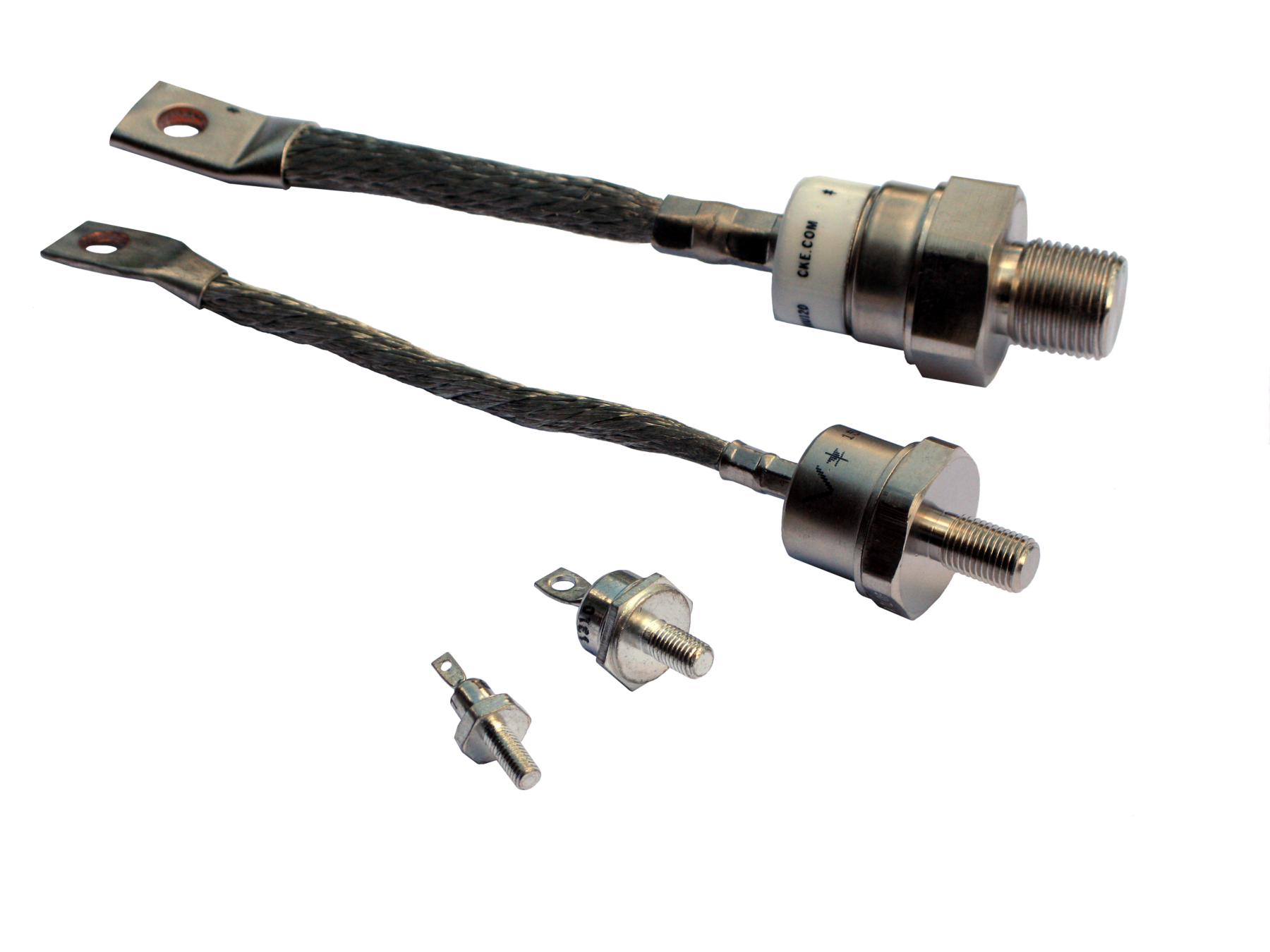
85HFL•60S02
Notes
- Current ratings require assembly on a suitably engineered heatsink, using a quality heat coupling compound.
- Data for all device parameters taken at 25˚C unless otherwise noted.
- Additional devices available on special request. Contact the factory.
- A "-" indicates a component that is a standard recovery device and no data was taken.
- For reverse polarity versions, replace the • with the letter "R" in the part number, e.g. 40HF•20 would become 40HFR20.
Specification
| DESCRIPTION | specification | conditions | VALUE |
|---|---|---|---|
| Maximum Repetitive Reverse Voltage | VRRM | 600 V | |
| Maximum Forward Voltage Drop | VF | At Rated IF | 1.75 V |
| Maximum Average Forward Current | IFAVM | At TC (Case Temperature) | 85 A |
| Maximum Allowable Junction Temperature | TJMAX | 125 °C | |
| Maximum Reverse Recovery Time | TRR | 200 nS | |
| Mounting Torque | T | Non-lubricated Installation | 20 - 30 in-lb |
| Maximum Case Temperature | TC | 75 °C | |
| Typical Thermal Resistance (Junction to Case) | RθJC1 | 0.3 °C/W | |
| Package Type | PACKAGE | DO-5 | |
| Maximum I2t For Fusing | I2T | At 60Hz | 5.523 |
| Low Level Forward Slope Resistance | RF1 | At TJMAX | 2.11 mΩ |
| Low Level Forward Threshold Voltage | VF(TO) | At TJMAX | 1.13 V |
| Maximum Reverse Leakage Current | IRRM | At TJMAX | 20 mA |

